How to Make a Traffic Light Using Arduino Uno (Beginner Project)🚦 ?
Welcome back to electronicmindset.com
If you are a beginner , then this article is the best for your weekend arduino project !
In this project,we'll build a simple traffic light system using Arduino UNO.It's a great beginner project to learn about programming, timing, and controlling multiple LED's.
Keep in mind, you will make a simple circuit with a simple code.
So Let's get started !
Table of contents
- How does our project work ?
- Components You Will Need 🛠️
- Circuit Diagram
- Write the Arduino Code 💻
- Upload the sketch
- Test the circuit
- How To Make It Better ?
How does our project work ?
So basically ,Our project works like a regular traffic light you see in the street:
Red LED (Stop): Turns on for 5 seconds. Green LED (Go): Turns on for 5 seconds. Yellow LED (Wait): Turns on for 2 seconds. This cycle repeats continuously, just like a real traffic light.
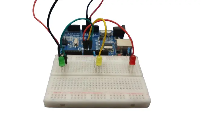
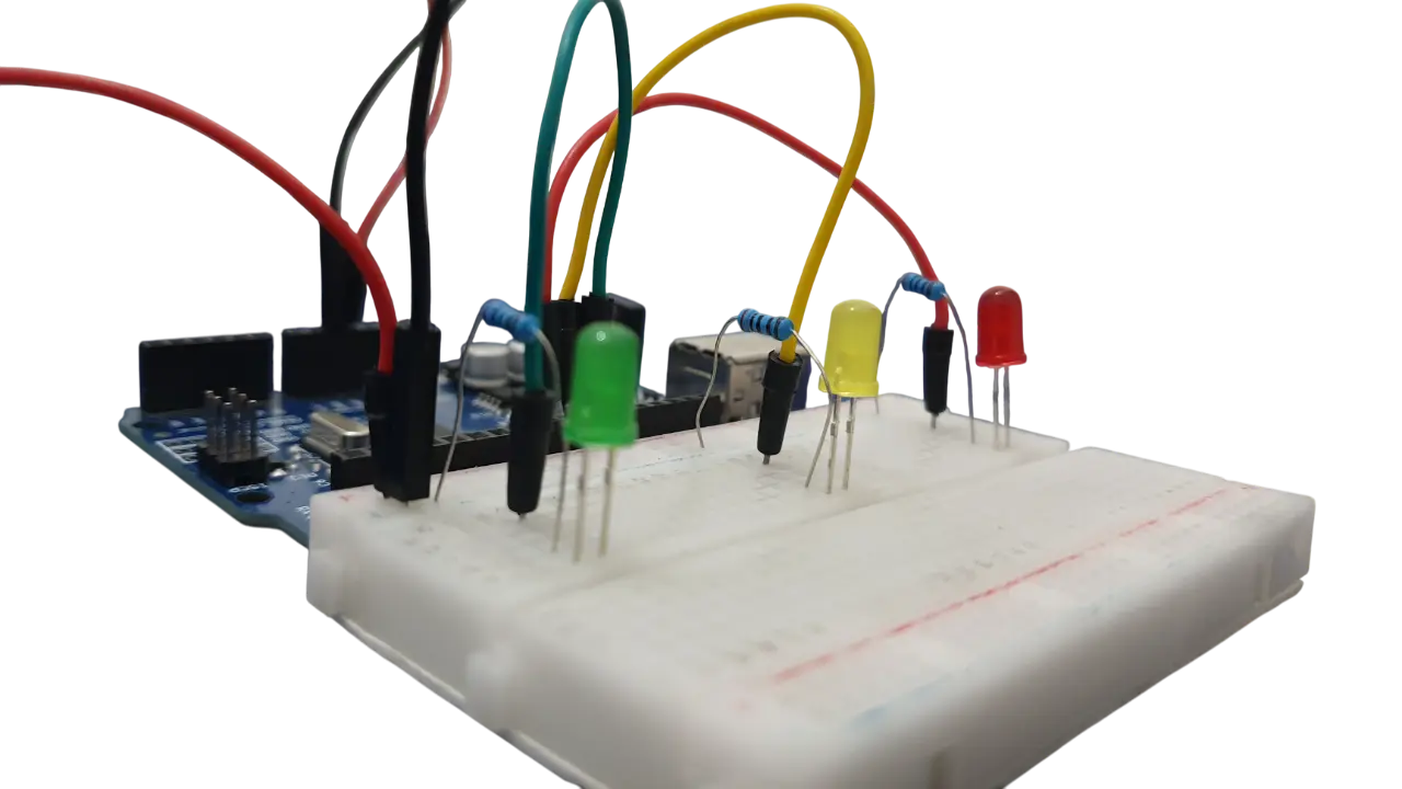
Prototype:
To make this project ,you have to follow these steps:
Step 1: Gather your materials.
You will need:

- 3 Led's(green, red, yellow)
- 3 of 220 ohms resistors
- breadboard
- Arduino Uno or any Arduino type
- Cable of arduino
- Jumper wires
- Laptop or computer
Step 2: Build the circuit.
Don't worry, building the circuit is very simple if you follow these steps
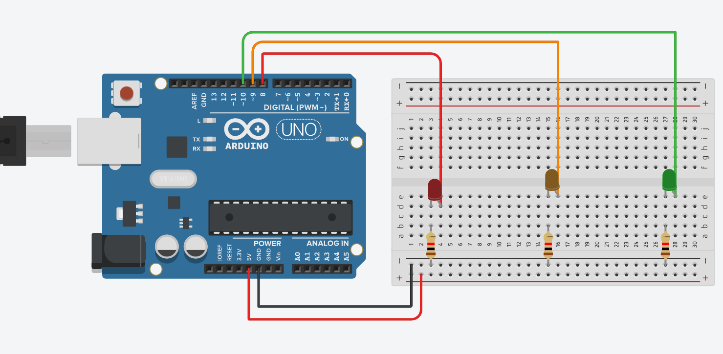
First, Place the three LEDs on the breadboard.
Connect the anode (long leg) of the red LED to pin 8 on the Arduino.
Connect the anode of the yellow LED to pin 9.
Connect the anode of the green LED to pin 10.
Connect the cathodes (short legs) of all LEDs to GND through a 220Ω resistor.
The shematics below will help you build the circuit just in case you don't understand:
Step 3: Write the code
Open the Arduino IDE on your computer, and write the following code:
// Source: https://electronicmindset.netlify.app/projects/traffic-light-using-arduino-uno
int red = 8;
int yellow = 9;
int green = 10;

void setup() {
  pinMode(red, OUTPUT);
  pinMode(yellow, OUTPUT);
  pinMode(green, OUTPUT);
}

void loop() {
  // Red light ON for 5 seconds
  digitalWrite(red, HIGH);
  delay(5000);
  digitalWrite(red, LOW);

  // Green light ON for 5 seconds
  digitalWrite(green, HIGH);
  delay(5000);
  digitalWrite(green, LOW);

  // Yellow light ON for 2 seconds
  digitalWrite(yellow, HIGH);
  delay(2000);
  digitalWrite(yellow, LOW);
}
Step 4: upload the sketch
First ,copy the code and paste it, then click on the checkmark icon (✓) on the top left corner of the IDE to verify that your code compiles without any errors.
Go to the "Tools" menu and select the appropriate board type ( Arduino Uno, Nano, etc...)
Then go to "Ports"submenu and select the port to which your Arduino board is connected. On Windows, it appears as COMx, and on macOS, it appears as /dev/cu.usbmodemxxxx.
Once the correct board and port are selected, click on the right arrow icon (→) next to the checkmark to upload the sketch to the Arduino board.
Use of a battery
The circuit that you have made is powered by your computer via the USB port.
If you want to power your arduino with 9V battery, make sure the positive terminal is connected to "VIn" pin in arduino and the negative terminal connected to "Gnd" pin .
Step 5: Test the Circuit
After uploading the code, you should your circuit working like a real traffic light !
Congratulations 🎉 You've just built your very own traffic light system with Arduino!
Improvements:
Ready to take your project to the next level? You can enhance your traffic light by adding a Traffic Light Module and a DC Buzzer for an audio alert.
Components Needed
You will need:
- Traffic Light Module
- DC buzzer
- breadboard
- Arduino Uno or any Arduino type
- Cable of arduino
- Jumper wires
- Laptop or computer
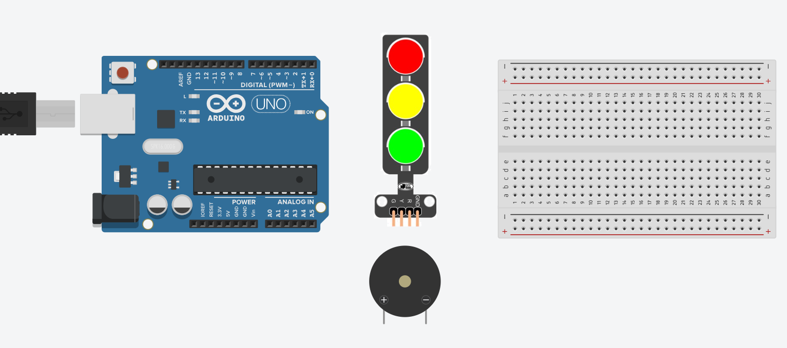
All you have to do is connect you components as it shown in the diagram below:
New Circuit Diagram

After connecting your circuit, upload this code to your Arduino board. This code has special functions to create unique sounds for each light sequence !
Improved Code
// Source: https://electronicmindset.netlify.app/projects/traffic-light-using-arduino-uno
// --- PIN DEFINITIONS ---
// LEDs
int redLedPin = 13;
int yellowLedPin = 12;
int greenLedPin = 11;
// Buzzer
int buzzerPin = 10; // Connect the positive pin of the buzzer here.

// --- SETUP FUNCTION ---
void setup() {
  // Set the LED pins as outputs
  pinMode(redLedPin, OUTPUT);
  pinMode(yellowLedPin, OUTPUT);
  pinMode(greenLedPin, OUTPUT);
  // Set the buzzer pin as an output
  pinMode(buzzerPin, OUTPUT);
}

// --- SOUND FUNCTIONS ---
// Plays a low, solid tone for a "stop" sound.
void playRedSound() {
  // The tone() function takes the pin, frequency (in Hz), and duration (in ms)
  tone(buzzerPin, 200, 1000); // 150 Hz tone for 2 seconds
}

// Plays a quick, high-pitched double beep for a "go" sound.
void playGreenSound() {
  tone(buzzerPin, 880, 200); // High pitch for a short time
  delay(250); // Pause briefly between beeps
  tone(buzzerPin, 880, 200); // Second high pitch beep
  delay(250);
}

// Plays a higher, warning tone that pulsates briefly.
void playYellowSound() {
  // Use a loop to create a pulsing effect
  for (int i = 0; i < 3; i++) {
    tone(buzzerPin, 440, 100); // Medium pitch for a very short time
    delay(150); // Short pause
    noTone(buzzerPin); // Stop the tone
    delay(100);
  }
}

// --- MAIN LOOP ---
void loop() {
  // Red light sequence
  digitalWrite(redLedPin, HIGH);
  playRedSound(); // Play the red sound
  delay(3000);
  digitalWrite(redLedPin, LOW);
  noTone(buzzerPin); // Stop any ongoing tone
  delay(500); // Small pause between sequences

  // Green light sequence
  digitalWrite(greenLedPin, HIGH);
  playGreenSound(); // Play the green sound
  delay(3000);
  digitalWrite(greenLedPin, LOW);
  noTone(buzzerPin);
  delay(500);

  // Yellow light sequence
  digitalWrite(yellowLedPin, HIGH);
  playYellowSound(); // Play the yellow sound
  delay(1000);
  digitalWrite(yellowLedPin, LOW);
  noTone(buzzerPin);
  delay(500);
}
Congratulations! You have just upgraded your circuit to a higher level
