How to use an RGB LED With the Arduino UNO
Welcome back to electronicmindset.com
In this tutorial,we will learn how to use a common rgb LED with arduino UNO and how to display multiple colors by using it.
Before starting, we have to undserstand what is an RGB led So let's start!
Table of contents
- What is an RGB LED ?
- 1. Gather Your Supplies
- 2. Construct the Circuit
- 3. Write the code
- 4. Upload the sketch
- 5. Observe the blinking
What is an RGB led?
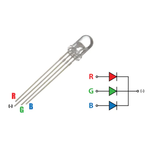
The RGB LED actually consists of 3 separate LEDs red, green and blue packed in a single case. That's why it has 4 leads, one lead for each of the 3 colors and one common cathode or anode depending of the RGB LED type.The RGB led can emit different colors by mixing the 3 basic colors red, green and blue. In this tutorial I will be using a common cathode one, which is the one that have the longer lead negative(-).
To make this project ,you have to follow these steps:
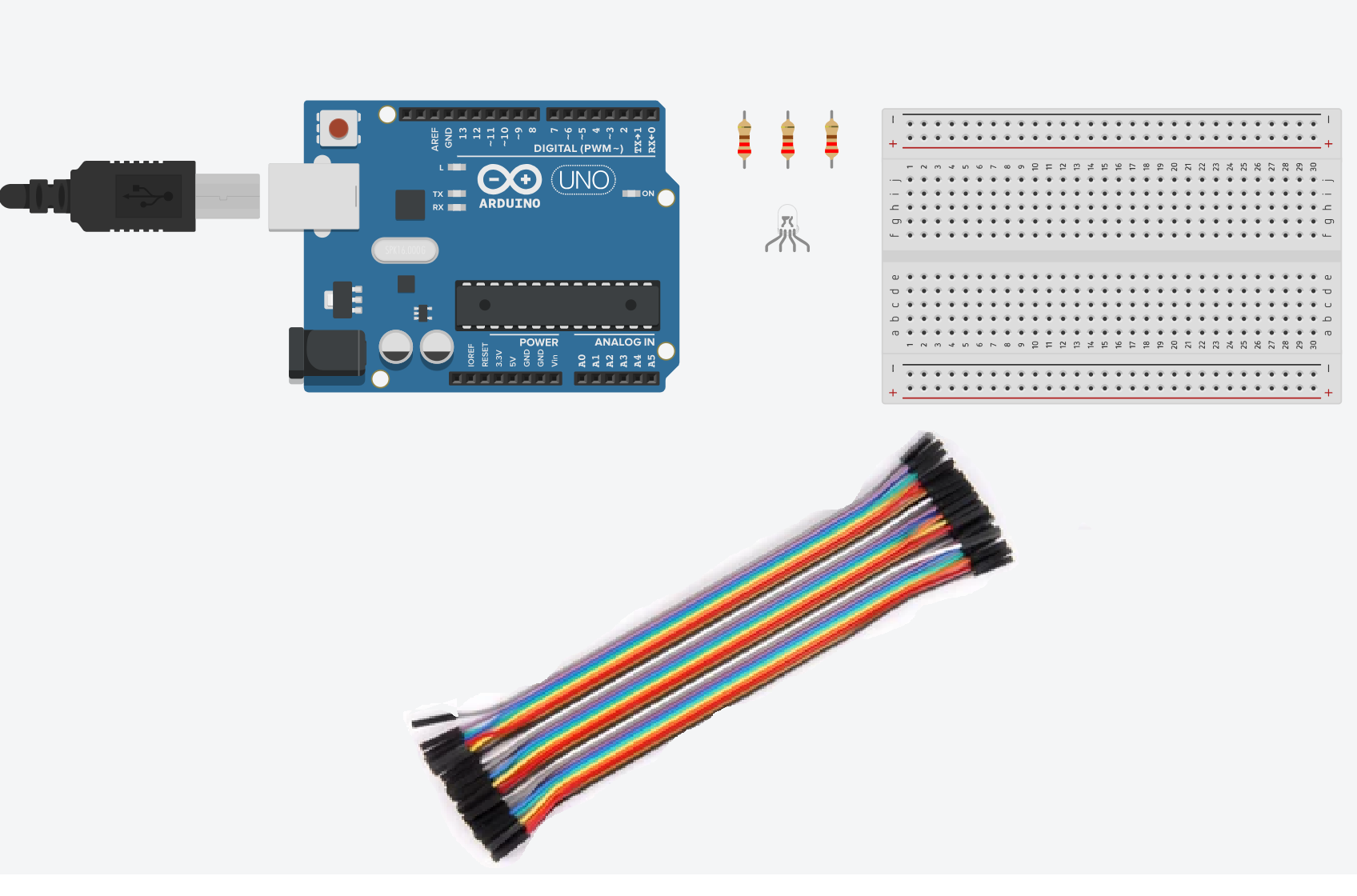
Step 1: Gather your materials.
You will need:
- An RGB led
- jumper wires
- breadboard
- Arduino Uno
- Cable of arduino
- 3 of 220 ohms resistor
- Laptop or computer
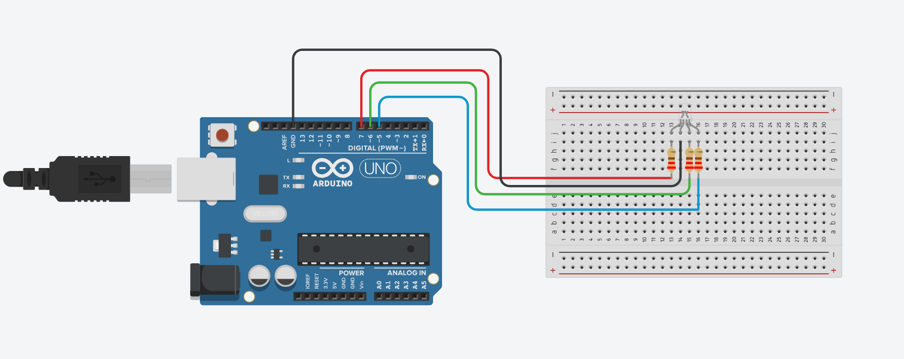
Step 2: Build the circuit.
First, place the RGB LED on the breadboard and connect the longer lead(cathode lead) to GND pin in arduino UNO.
Connect each of the shorter legs (anodes) to a resistor (220 ohms) and then connect the other end of each resistor to Arduino's digital pins.
Red led pin to digital pin 7
Green led pin to digital pin 6
Blue led pin to digital pin 5
Shematics
Step 3: Write the code
Open the Arduino IDE on your computer, and write the following code:
					// Define the pins for Red, Green, and Blue LEDs
int redPin = 7;
int greenPin = 6;
int bluePin = 5;

void setup() {
  // Set the LED pins as OUTPUT
  pinMode(redPin, OUTPUT);
  pinMode(greenPin, OUTPUT);
  pinMode(bluePin, OUTPUT);
}

void loop() {
  // You can adjust the values (0-255) to change the color
  setColor(255, 0, 0);   // Red
  delay(1000);            // Wait for 1 second

  setColor(0, 255, 0);   // Green
  delay(1000);

  setColor(0, 0, 255);   // Blue
  delay(1000);
}

// Function to set the RGB LED color
void setColor(int red, int green, int blue) {
  analogWrite(redPin, red);
  analogWrite(greenPin, green);
  analogWrite(bluePin, blue);
}
The code was pretty straightforward and clear, This code sets up the Arduino Uno to control an RGB LED, sequentially displaying red, green, and blue colors with a delay of 1 second between each color change.
Here's a breakdown of what each part does:
- THe first part, define variables redPin, greenPin, and bluePin to represent the digital pins on the Arduino Uno to which the RGB LED's red, green, and blue legs are connected respectively.
- Then, configure the LED pins as OUTPUT in the setup() function.
- In the loop() function, call the setColor() function three times with different RGB values to display red, green, and blue colors sequentially.
- Use delay(1000) to wait for 1 second between each color change.
- Define the setColor() function to set the intensity of each color component (red, green, blue) using PWM on the respective pins. The function takes three arguments: red, green, and blue, each ranging from 0 to 255.
- Inside the function, use analogWrite() to output PWM signals to the respective pins, controlling the brightness of each LED.
Step 4: upload the sketch
First ,copy the code and paste it, then click on the checkmark icon (✓) on the top left corner of the IDE to verify that your code compiles without any errors.
Go to the "Tools" menu and select the appropriate board type ( Arduino Uno, Nano, etc...)
Then go to "Ports"submenu and select the port to which your Arduino board is connected. On Windows, it appears as COMx, and on macOS, it appears as /dev/cu.usbmodemxxxx.
Once the correct board and port are selected, click on the right arrow icon (→) next to the checkmark to upload the sketch to the Arduino board.
Use of a battery
The circuit that you have made is powered by your computer via the USB port.
If you want to power your arduino with 9V battery, make sure the positive terminal is connected to "VIn" pin in arduino and the negative terminal connected to "Gnd" pin .
Step 5: Observe the RGB led
Once the sketch is uploaded, you should see the RGB LED changing colors according to the defined sequence (red, green, blue) with a delay of 1 second between each change.
That's it! You've successfully uploaded a sketch to control an RGB led using an Arduino.
